Normal maps and TBN
When rendering with any consideration for the directions surfaces are facing, such as almost any time that lighting is involved, having or calculating a polygon’s normal vector becomes effectively necessary.
For a quick overview; a surface normal is effectively a vector that points directly out of any point on a surface, you could think about it in terms of the direction that part of the face is flatly towards. When discussing normals you may commonly see surface normals being shown as a line or arrow coming out of the surface.
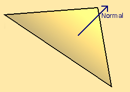
Above: a diagram of a triangle in 3D space, with its surface normal represented by an arrow.
While the normal can exist for any point on a surface; when stored they are usually recorded per vertex, per face, this usually consistent across the face but can differ if the appearance of a curve is desired when interpolating between them.
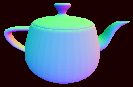
Above: a teapot model whose normal vectors are visible as RGB color.
This kind of visualisation is useful for checking that the normals make sense on a per fragment scale in a feasible way. This data is on the GPU’s end so it is in some sense more distant than other areas of memory, and there can easily be millions on your screen at any one time so checking individual values would be more than a little obtuse. Putting the surfaces in a comprehensible environmental context also helps.
In terms of actual utility; A prolific use of normals would be in the context of reflection of the light direction based on the normal to determine how lit a surface is. This can be enough, but in this form is entirely reliant on the geometry, meaning that extra detail comes with substantial processing cost.
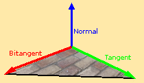
Modifying the surface normal on a texture or fragment level requires the further context of directions that the texture is going to be modifying the normal in. For the most part these direction vectors point along the surface and align with the orientation of the surface’s texture or UV. As they exist as 2 directions, and function relative to the normal, they would be the ‘tangent’ and ‘bitangent’. Both the ‘tangent’ and ‘bitangent’ can be expected to be vectors 90 degrees from the normal vector, and usually 90 degrees from each other unless the UV is skewed or distorted.
If there is any form of generation or modification of model UVs then it will be necessary to be able to calculate the correct ‘tangent’ and ‘bitangent’ from the geometry. I am sure it can be improved, but here is the procedure for how I do this as of writing this:
vertexDeltaA = vertexA - vertexC
vertexDeltaB = vertexB - vertexC

textureCoordinatesDeltaA = textureCoordinatesA - textureCoordinatesC
textureCoordinatesDeltaB = textureCoordinatesB - textureCoordinatesC

reciprocal = 1 / (textureCoordinatesDeltaA.x * textureCoordinatesDeltaB.y - textureCoordinatesDeltaA.y * textureCoordinatesDeltaB.x)

tangent = reciprocal * (textureCoordinatesDeltaB.y * vertexDeltaA - textureCoordinatesDeltaA.y * vertexDeltaB)

bitangent = reciprocal * (-textureCoordinatesDeltaB.x * vertexDeltaA + textureCoordinatesDeltaA.x * vertexDeltaB)
Now that we have the ‘tangent’ and ‘bitangent’ available to us we now need to be able to define where and where they are being used. I would say that the most common way of utilising these on a fragment scale would be through the use of a normal map.

Above: an example of a normal map.
In a normal map each directional axis has a color channel, and converted to clip space (a range from -1 to 1) these can be multiplied by the ‘tangent’ and ‘bitangent’ respectively and applied to the normal vector to slightly change its direction.
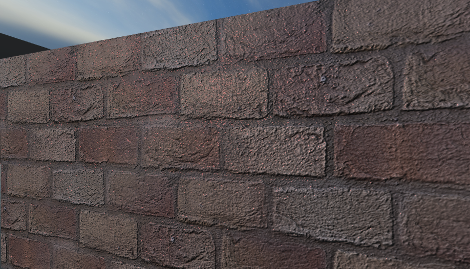
The outcome is a relatively low cost contours to improve the look of a texture or material.